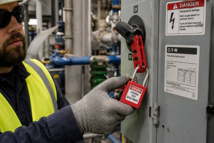
The Emergency stop function must be designed so that after acting on the emergency stop operating device, the dangerous movements of the machine are stopped. We are within the scope of Industrial Safety And in this field, at Grupo TICE, we are experts. In line with this, the first thing to do is to determine a correct level of emergency stop performance, which will be defined based on the severity of a hypothetical injury (and its consequences) and the frequency with which such a dangerous situation can occur, among other variables.
Therefore, and as we say, a potential accident can cause very severe personal injury, even death, so it is unacceptable for the activation of an emergency stop to fail.
This is why, on occasion, simply cutting the relay(s) that operate the machine may not be enough.
For example, a standard relay It can fail for different causes, causing the contacts to become fixed and preventing it from opening the circuit in an emergency.
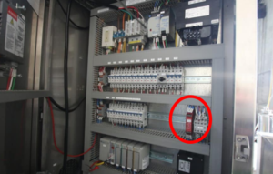
Furthermore, the control logic of a safety module prevents, for example, its safety function from being deactivated in the event of a component failure. Not only that, but the electrical circuit is redundant at several nodes, making it practically impossible (or at least very unlikely) for said module to fail. Let's look at what this circuit consists of and how to connect it correctly.
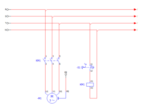
For this essay, we will be using the OMRON G9SB model. Basically, apart from more complex drive systems, such as those for photoelectric barriers or inductive sensors, the wiring is straightforward.
First, we will look at the wiring of the mushroom. If we look closely, we can see that the manufacturer requires the mushroom to have 4 NC connection points (normally closed) which will have to be linked together, or in other words, both must open at the same time when activated, otherwise, the module will not close some of the contacts that are in series.K1’’ and K2’’).
Another striking fact is that the manufacturer uses a lockable push button.
Let's see how the circuit behaves the moment we activate the emergency stop and we'll see if it's necessary for the mushroom to remain locked, keeping the circuit open until it's unlocked.
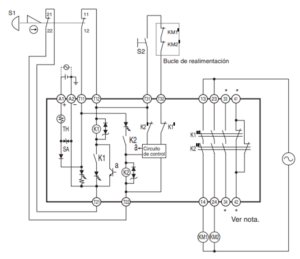
While S1 Do not actuate, the coils K1 y K2 (redundant coil) are kept active (shorted) by closing the contacts K1’’ and K2’’ and maintaining tension in KM1 y KM2.

The contacts remain open as well. KM1 and KM2’ in the feedback loop. Note that they are in series with S2 (rearview mirror). We'll then look closely at its behaviour.
Please note that the diodes are in parallel with the coils K1 y K2 They have disappeared. This has been done to make them easier to interpret. The diode remains in cutoff, so no current reaches the Zener diode either. The photodiodes (LEDs) remain forward-biased and illuminated.
When we press the emergency mushroom switch, the circuit powering the coils K1 y K2 enters into contact and no current flows (remember they are normally open, their natural state if no voltage is applied), just like the rest of the contacts, which also return to their natural state.

Even if we un-enclosed and re-entered into contact S1, restoring continuity to the circuit, the coils K1 would not be activated, so the contact K1’’ nor. The explanation is in the transistor placed in series (a) which conducts (since the control circuit is powered by K2’ so that the current takes that “bridge” path (current takes the easiest path), avoiding its supply.
The reset must be pressed (applying voltage to the feedback loop causing K1’, K2’, KM1’ and KM2’ to open) so that no base current reaches the BJT, it enters cut-off and returns the voltage to K1. From that moment on, the contacts Normally Open / Normally Closed they return to their resting state (closing and opening respectively) and leaving the circuit ready for a “start” button to close the circuit, sending voltage to the auxiliary contacts of KM1 y KM2 and start the engine.
Francisco V. Campos Ramos - Industrial Electronic Engineer from Grupo Tice